 |
| Hall sensor symbol |
What is a Hall effect sensor?
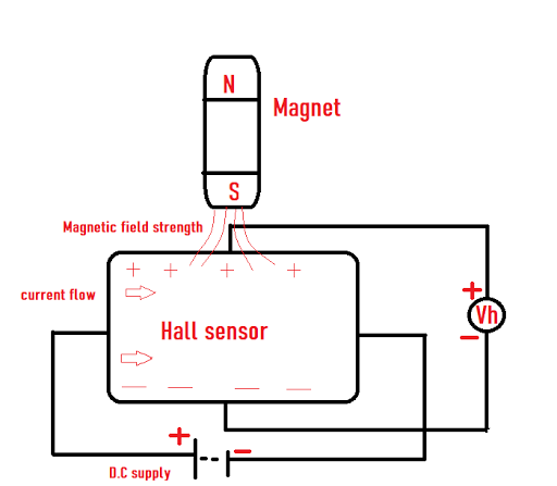
Hall effect sensor is defined as a device which use the principle to convert magnetically encoded signals into electrical signals. Which means Hall effect sensor output voltage is directly proportional to the magnetic field strength. Hall effect sensors are used in automotive systems for sensing distance, position, speed detection, and current sensing applications.
 |
| Hall effect sensor working principle |
Suppose the sensor is placed inside a magnetic field and the magnetic flux lines in the magnet can exert a force on the P-type semiconductor material, which deflects the charge carriers, electrons and holes on either side of the semiconductor layer. This is an event that happens due to the gravitational force of the magnet.
As stated before, when a beam of charged particles passes through a magnetic field, forces act on the particles and the beam is deflected from a straight path. When a conductor is placed in a magnetic field perpendicular to the direction of the electrons, they will be deflected from a straight path. As a consequence, one plane of the conductor will become negatively charged and the
opposite side will become positively charged. The voltage between these planes is called the `Hall voltage´.
Hall's effect theory gives us information about the type of magnetic pole and the magnitude of the magnetic field. For example, a south pole will produce the device voltage output, while the North Pole will have no effect. Generally, Hall Effect sensors and switches are basically designed to be in the “NO” condition (normally open) when there is no magnetic field present. They only
change to "NC" (normally closed) when carried close to a magnetic field of sufficient strength and polarity.
Hall effect sensors types
 |
| Scheme circuit connection |
There are two types of Hall effect sensors: Devices with linear or analogue outputs, and those that have digital outputs. Analogue sensors use a continuous voltage output that increases within a strong magnetic field and decreases in a weaker field.
With linear output Hall effect sensors, as the strength of the external magnetic field increases when the sensor device interacts with the magnet, the output signal increases in parallel until it reaches the limits imposed by the power supply.
The digital output device, has a ‘Schmitt trigger’, which is a bi-stable circuit that
steadily increases and decreases the output when the voltage rises and falls to different thresholds.
Applications of Hall effect sensor:
Anti-skid sensor:
For this application a biased Hall effect sensor is used. The sensor is positioned to sense an internal tooth gear. The gear could be the disk brake hub.
The reaction time of the braking system will determine the frequency of the signal as a function of wheel revolution.
 |
| Anti skid sensor |
 |
| Door lock and ignition sensor |
Figure illustrates a concept that uses a digital output bipolar sensor and magnets mounted to an impeller to measure flow rate for a water softener. In this design, the softener can be made to automatically recharge on demand, instead of on a timed basis. Demand is determined by measuring the amount of water that has passed through the softener. When a certain level is reached, the recharge cycle begins.
 |
| Flow rate sensor |
Office machines are designed to operate more reliably than ever before. This sensor is used in copiers, fax machines, and computer printers.
Magnetic card reader:
In this example the card slides-by the sensor producing an output. This analog signal is converted to digital, to provide a crisp signal to operate the relay. When the relay’s solenoid pulls-in, the door can be opened.
For systems that require additional security measures, a series of magnet can be molded into the card. A constant speed motor-driven tray slides this multi-coded card past the sensor or an array of linear output sensors, generating a series of pulses. These pulses are addressed to a decoding unit that outputs a signal when the correct frequency is present. Or it could generate a multi bit encoded function that allows entry to selected units.
 |
| Magnetic card reader |
In pressure sensing, a magnetic assembly is attached to a bellows assembly. As the bellows expands and contracts, the magnetic assembly is moved. If the sensor is placed in close proximity to the assembly, an output voltage proportional to pressure input can be achieved.
Temperature measurement works similarly to pressure, except that a gas with a known thermal
expansion characteristic is sealed inside the bellows assembly. As the chamber is heated, the gas expands causing a voltage from the sensor that is proportional to the temperature.
 |
| Temperature or pressure sensing |

Comments
Post a Comment